Proceedings of the Combustion Institute, 2000: Imaging of CO and CO2 using infrared planar laser-induced fluorescence
Citation:
Kirby BJ, Hanson RK, Imaging of CO and CO2 using infrared planar laser-induced fluorescence, Proceedings of the Combustion Institute, 28:253-259 (2000). doi pdf
Abstract:
Infrared (IR) planar laser-induced fluorescence (PLIF) techniques for imaging of carbon monoxide and carbon dioxide are reported. These diagnostics employ a tunable IR source to excite overtone and combination band transitions of CO and CO2, respectively, and one or two InSb focal plane arrays to collect fluorescence emitted via fundamental transitions from excited vibrational states. A brief outline of the theoretical framework for absorption and fluorescence modeling is presented, with most attention paid to the distinct characteristics stemming from the use of vibrational (IR) transitions as compared to more traditional electronic (UV) transitions. Of note are the conclusions that (1) acceptable fluorescence quantum yield (and therefore signal level) can be achieved despite relatively small Einstein A coefficients, as the quenching processes following IR excitation are often slow; and (2) vibration-to-vibration transfer to
other IR-active species can enable imaging of more than one species with a single excitation wavelength. Experimentally, the large dynamic range afforded by the IR cameras (14 bit) allows for effective imaging despite the presence of background luminosity, while the use of two cameras enables imaging of multiple species simultaneously and/or common-mode rejection of luminous background in unsteady flows. PLIF imaging of CO and CO2 is demonstrated for room-temperature mixing processes with signal-to-noise ratio = 1 detection limits near 1000 ppm. Imaging of both CO and CO2 in a steady laminar coflowing CO/Ar/H2 flame is also presented using laser excitation of CO only.
Figures:
-
- Fig. 1. Single-shot CO and CO2 IR PLIF images. CO at left indicates the fuel region of a steady laminar coflowing CO/H2-air flame. CO2 at right is a forced room-temperature jet issuing into air. doi pdf
-
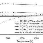
- Fig. 3. Calculated characteristic times (1/transfer rate) of VET from CO to common species as a function of temperature at 1 atm. Components which remove energy from CO are shown with symbols, and the total transfer is summed as the solid line. The dashed line indicates CO- CO V-V transfer which tends to equilibrate the CO vibrational mode but does not serve as a quenching mechanism. doi pdf
-
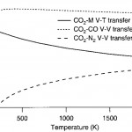
- Fig. 4. Calculated characteristic times (1/transfer rate) of VET from CO2 to common species as a function of temperature at 1 atm. doi pdf
-
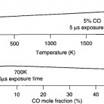
- Fig. 5. CO fluorescence quantum yield as a function of temperature and composition for the simplified case of CO in N2. doi pdf
-
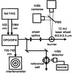
- Fig. 6. Experimental setup for imaging experiments. PBS, pellicle beamsplitter. InSb cameras (Santa Barbara Focalplane SBF134) have the following characteristics: 0.7-5.3 micron sensitivity range; 30-micron pixels; 85% quantum efficiency; 130 ns minimum integration time setting; 300 Hz maximum frame rate. doi pdf
-
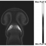
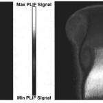
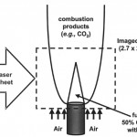
- Fig. 8. Single-shot IR PLIF image of a forced 6 mm diameter jet. Jet fluid is 40% CO2/60% Ar. 12 mJ excitation of CO2 at 2.0 microns; CO2 fluorescence collected at 4.3 microns. Integration time is 20 microsec. Ambient gas is air. doi pdf
-
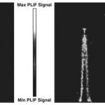
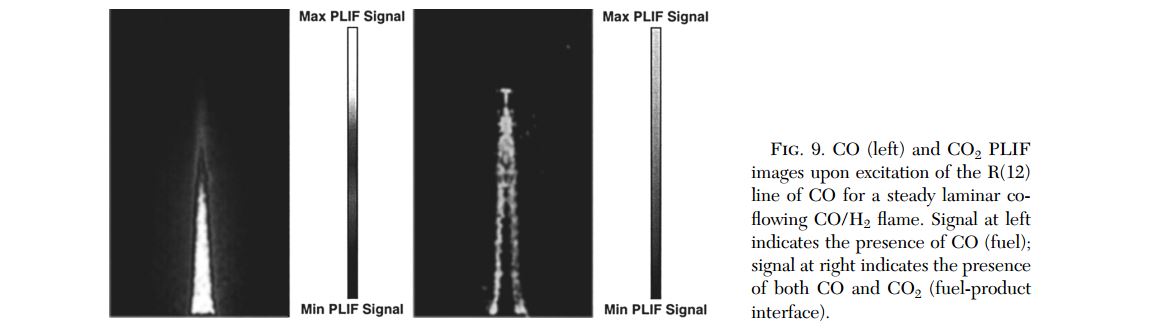
- Fig. 9. CO (left) and CO2 PLIF images upon excitation of the R(12) line of CO for a steady laminar co- flowing CO/H2 flame. Signal at left indicates the presence of CO (fuel); signal at right indicates the presence of both CO and CO2 (fuel-product interface). doi pdf