Rare cell capture from blood is exciting owing to the potential to derive clinical benefit with minimal inconvenience and discomfort to patients. Information derived from rare cells (e.g., fetal cells in mothers or cancer cells in cancer patients) can be used in lieu of information from biopsies and thus improve patient outcomes.
Microfluidic devices are ideally suited for these processes, owing to the flexibility of geometric design, wealth of chemical manipulation techniques, and assay compatibility of current systems. Stokes flow analysis is often a good predictor of the flows in these systems.
A selection of figures from relevant publications are below. Click to open a carousel view. Links to the original manuscript are in the captions.
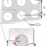
FIG. 1. Antibody-functionalized obstacle arrays in a 2D microfluidic device can be used to engineer differential particle
transport. This paper studies the effect of DEPassisted
immunocapture, generated by applying an AC electric field to electrodes offset from the array and parallel to the
direction of fluid flow. Target cells undergoing positive DEP (pDEP) are attracted to the high electric field magnitude
regions at the obstacles leading and trailing edges (right inset), where the shear stress is low and the residence time is long
(supporting the capture of the target cells); although they are also repelled from the low field magnitude regions at the obstacle
shoulders, the locally high shear stress and short residence time minimizes the impact on overall capture. Likewise,
contaminating cells undergoing negative DEP (nDEP) are repelled from regions where capture is likely (i.e., the obstacles’
leading edge) and attracted to regions where capture is unlikely (i.e., the obstacles’ shoulder).
Fig. 5 (a) Off-design boundary conditions, such as from a clogged
inlet channel or a lump of captured cells near the inlet, can lead to a
transverse velocity error; this additional velocity
component alters trajectories within the array. doipdf
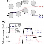
FIG. 2. DEP alters cell trajectories within the microfluidic device, leading to changes in the mean collision frequency for
cells within a given device geometry. Advection dominates DEP at the obstacles’ shoulder, but the reverse is true at the
obstacles’ leading and trailing edges, where the fluid flow stagnates; as such, a cell’s response in the high electric field magnitude
region at the leading and trailing edges has the most effect on its trajectory through the array. For medium and large
cells (e.g., diameters B and C in this figure), pDEP attracts the cells to the high field magnitude regions near the leading
and trailing edges, increasing the mean collision frequency and the time in contact (which supports capture), whereas
nDEP (fCM < 0) repels cells from these regions. Likewise, pDEP forces small diameter cells (e.g., diameter A) toward the
region of high field magnitude, increasing collision frequency compared to without DEP, but the overall collision frequency
remains low. Although nDEP does indeed repel these small cells from the high field magnitude regions, nDEP displaces
particle diameter A enough to cause a brief “grazing” cell-obstacle collision, increasing the collision frequency; these grazing
events are brief and occur where the shear stress is highest, so capture of these cells is unlikely.
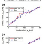
Fig. 6 (a) Particle tracking experiments and comparison to simulated
transfer functions for various transverse errors allow for the quantification
of error along the length of the obstacle array, shown in a planview
schematic here. doipdf
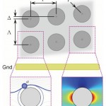
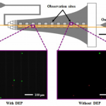
FIG. 1. Schematic of the Hele-Shaw flow cell and its interdigitated electrodes with lead connections to an applied voltage
(6V) and ground (GND), and elongated straight inlet channel compared to previous designs.35,37 The elongated straight
inlet channel was 500 lm wide, the smaller branching channels were 156 lm wide, and all channels were 48 lm tall. The
main chamber geometry leads to a monotonically decreasing shear stress along the device centerline, which allows for cell
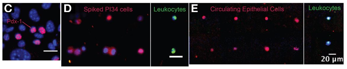
capture to be measured as a function of shear stress.40–42 Inset images show fluorescently labeled PANC-1 cells (green) and
PBMCs (red) adhered to the antibody-functionalized surface with and without DEP effects. These example images show
that at an applied AC electric field frequency of 200 kHz, more PANC-1 cells and fewer PBMCs were captured with DEP
compared to without DEP. Captured cells in each pair of 1-mm2 observation windows were enumerated and compared at a
series of observation sites corresponding to a range of shear stresses found in typical immunocapture devices.4,12,39,43
Fig. 1 A two-dimensional array of cylindrical obstacles in a microfluidic
device generates size-dependent cell transport. doipdf
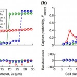
Fig. 3 The transfer function model (symbols) closely agrees with the
full CFD simulation (lines) for both (a) collision frequency and (b)
capture probability using LNCaP prostate cancer cells and a device
with N = 100 unit structures for a range of offsets. doipdf