Lab-on-a-chip devices (also known as micro-total-analytical systems or microTAS) are devices designed to miniaturize analytical or bioanalytical techniques and integrate them into a microfabricated format. Techniques such as chemical separations (electrophoresis, chromatography, etc) or immunoassays are incorporated into microfabricated systems (typically glass, silicon or polymers) with a goal of increasing performance, minimizing reagent requirements, and decreasing cost. BioMEMS devices are similar, typically focusing on MEMS (microelectromechanical systems) with biological applications.
We use lab-on-a-chip devices to capture, sort, culture, or study cells, study interfacial phenomena, and produce pharmaceuticals.
A selection of figures from relevant publications are below. Click to open a carousel view. Links to the original manuscript are in the captions.
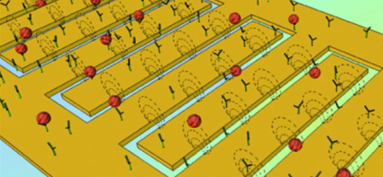
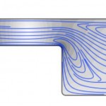
FIG. 1. Antibody-functionalized obstacle arrays in a 2D microfluidic device can be used to engineer differential particle
transport. This paper studies the effect of DEPassisted
immunocapture, generated by applying an AC electric field to electrodes offset from the array and parallel to the
direction of fluid flow. Target cells undergoing positive DEP (pDEP) are attracted to the high electric field magnitude
regions at the obstacles leading and trailing edges (right inset), where the shear stress is low and the residence time is long
(supporting the capture of the target cells); although they are also repelled from the low field magnitude regions at the obstacle
shoulders, the locally high shear stress and short residence time minimizes the impact on overall capture. Likewise,
contaminating cells undergoing negative DEP (nDEP) are repelled from regions where capture is likely (i.e., the obstacles’
leading edge) and attracted to regions where capture is unlikely (i.e., the obstacles’ shoulder).
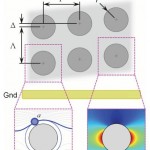
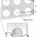
Fig. 1 A two-dimensional array of cylindrical obstacles in a microfluidic
device generates size-dependent cell transport. doipdf
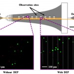
Figure 1. Schematic of the Hele-Shaw flow cell and its interdigitated electrodes with lead connections to an applied voltage (+/-V) and ground (GND). Inset images show fluorescently labeled LNCaPs (green) and PBMCs (red) adhered to the antibody-functionalized surface
with and without DEP effects. These example images show that at an applied AC electric field frequency of 350 kHz, more LNCaPs and fewer PBMCs are captured with DEP as compared to without DEP. Captured cells in each pair of 1-mm2 observation windows were enumerated
and compared at a series of observation sites corresponding
to a range of shear stresses. Details of the device geometry and shear stress distribution are described in our previous work (Huang et al. 2013). doipdf
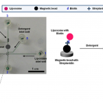
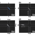
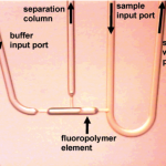
Fig. 1 Image of the integrated glass microfluidic device used for the biotin–streptavidin experiments, with the channels filled with food dye to show contrast. The inset shows a picture of the polyacrylamide membrane-based concentrator at the junction of microchannels. Biotinylated liposomes are captured by streptavidin-conjugated magnetic beads localized at the magnet. The fluorescence from the lysed liposomes is imaged downstream from the magnet in the region marked as the fluorescence measurement window.
Fig 2 Image sequence showing liposome concentration and elution. Microchannel edges have been drawn for clarity. The membrane has also been highlighted in (a). HV high voltage (100 V), PV pinch voltage (40 V), Gnd ground. (a) Before loading; (b) Sample concentration; (c) After concentration; (d) Sample elution. Pinch voltage is applied to minimize the diffusion of the sample away from the membrane
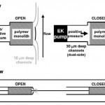
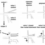
Four-port valve allowing rapid sample changes. Sample
is changed by flushing at low pressure when the sample waste port
is open. Sample is injected by closing sample waste port and
pressurizing the sample line.
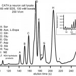
Fig. 5 MEKC separation of primary amines from a multiple-cell CATH.a neuron cell lysate on glass treated with the SAM. NE: norepinephrine. Inset:
separations under the same conditions using bare glass. Separation fidelity and retention time repeatability are similar in the two cases; increases in zeta
potential caused by wall-detergent interactions upon coating with SAM lead to reduced elution times in the SAM-coated case. doi pdf
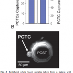
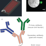
a) Schematic overview of the GEDI device, modified from Kirby et al.,18 microposts not to scale b) calcein-stained (green) PANC-1 cell captured on a GEDI micro post functionalized with a cancer-specific MUC1 antibody. Scale bar: 20 μm c) silicon surface functionalization with primary antibodies and secondary antibody linker chemistry that allows for multiple parallel capture antibodies
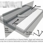
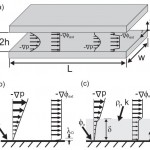
FIG. 1. Diagrammatic representation of the system under consideration. (a): Geometric definition of the parallel-plate system studied; plates of width w and lengthLare separated by a distance 2h. Included are shapes of pressure-driven and electrically forced flows for (left) a channel with rigid surfaces and (right) a channel with a porous lining. In (b) and (c), magnified diagrams at the surface detail distributions of velocity and potential for a bare, rigid surface (b) and a surface with a porous layer of thickness delta(c).doipdf