By Taru
AutoCad and ArcGIS were used to create shapefiles representing pavilions, roads, and landscape features from a scanned historical site plan of the 1964-65 World’s Fair. These shapefiles were later imported into CityEngine. The following steps provide an overview of the process of going from scanned site map to shapefile ready for import.
Step 1
Merge the jpegs drawing in Adobe Photoshop/Illustrator to create a complete map
The site plan was available in a pdf, presented on two different pages. To create a complete map, the two images had to be merged. This was done by printing each page separately and bringing them to Adobe Photoshop/Illustrator. Since I wanted to create a vector version to line trace, I opened the two files in Illustrator and merged the files by opening them in the same file and aligning them on a page. The image was saved as a pdf.
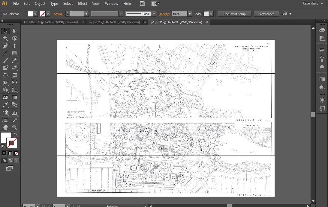
This step can be skipped and the merging of the line out drawings can also be done in Auto cad. This can be done by importing/inserting the pdf as background and tracing. The line outs can then be scaled appropriately, using the same units and merged by using object snap and move tools.
Step2
Creating a Vector Drawing of the image
A vector drawing of the complete map from 1964 can be useful in recreating the cultural landscape digitally and compare it geospatially with the current day plans.
Process A: Using Illustrator
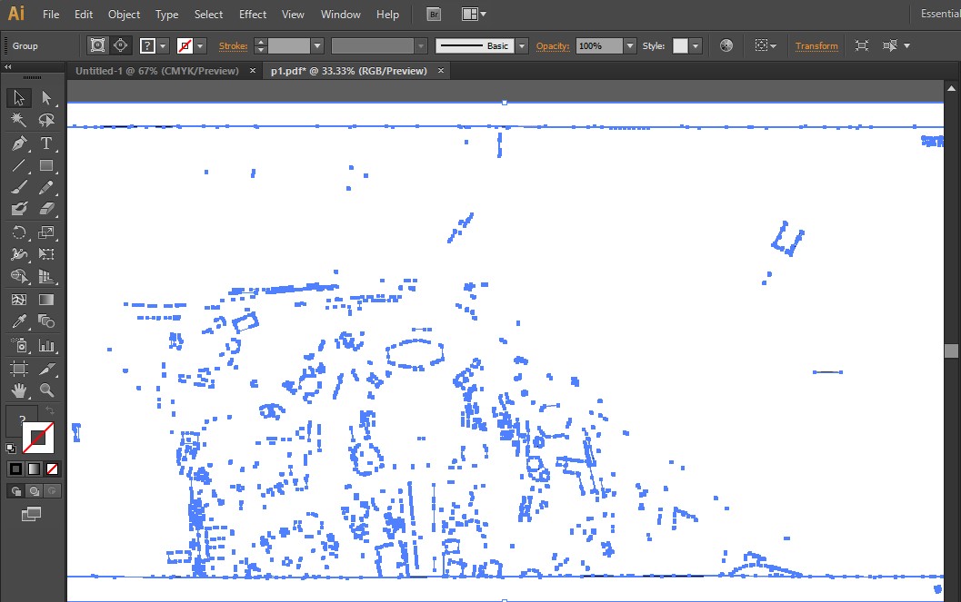
I imported the image to illustrator and used the object-image trace option to create vector version of the drawing. If this had worked, I could have simply taken line tracing to cad and assigned layers. Ideally, this would be the way to proceed as it would save a lot of time by auto tracing.
In this case, however, the resolution of the image was low and lines were therefore pixelated. The image trace resulted in a fragmented line out that would not be of any use. It thus became necessary to create a line out manually and AutoCAD is the most useful software to accomplish this.
Process B: Using Auto cad
a) Importing the jpeg into Auto cad and scaling it
The combined pdf/ jpeg can be used as a background image to create a line out drawing. One can either import a jpeg or they can link the image as a background image by either using Insert attach or Insert Import. It is easier to work with Insert attach as it only links the pdf file and does not bring the entire image in to the CAD drawing. In this case. Linking the drawing keeps the file from becoming too bulky.
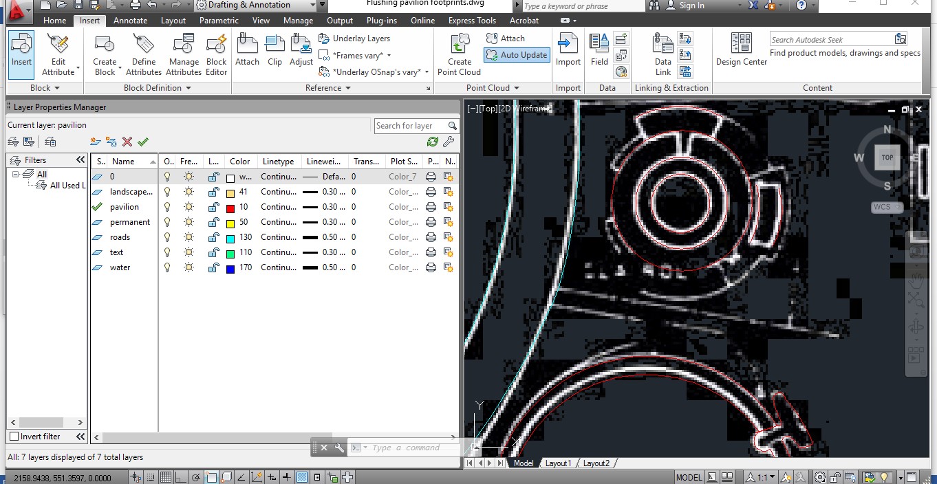
b) Creating Layers
The line drawings needed to be drawn in layers so that they can easily be converted to relevant shapefiles. In this case, one can create relevant layers by the type of physical feature, like pavilion, landscape and roads.
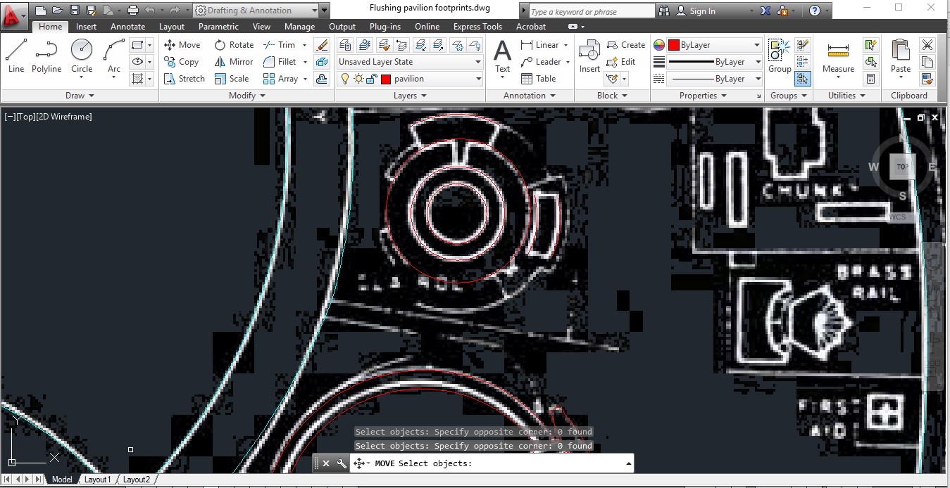
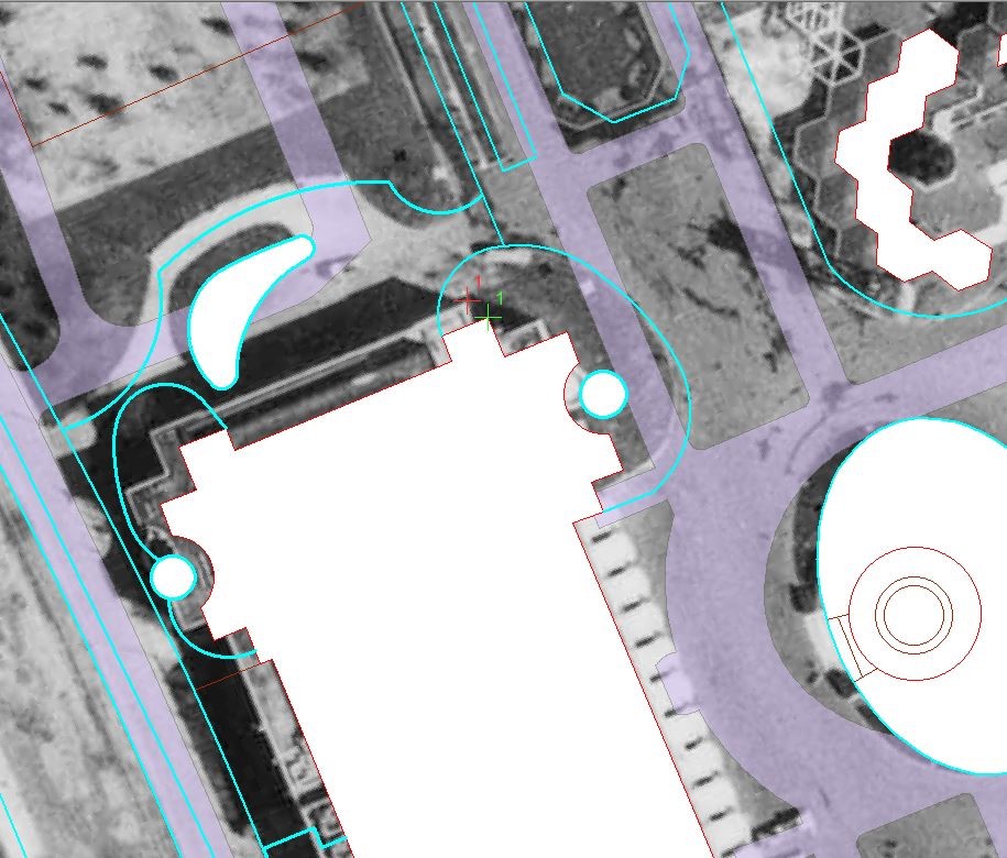
c) Tracing the drawing using polylines
Using the p-line or sp-line tools are the best tools to use.
d) Things to be Careful About
- Assigning geographic coordinates in Auto cad can lead to transitioning issues with GIS. It is best to add them in ArcGIS.
- Using Completed line loops is important or the files will not change to polygon shape files and will therefore require major re-editing during the transition.
- Using the right units and scale (in keeping with the rest of the files) helps the aligning of the project.
- Using the right layers in cad lets us differentiate shapefiles better.
Step 3 Importing into GIS and Aligning with existing Files
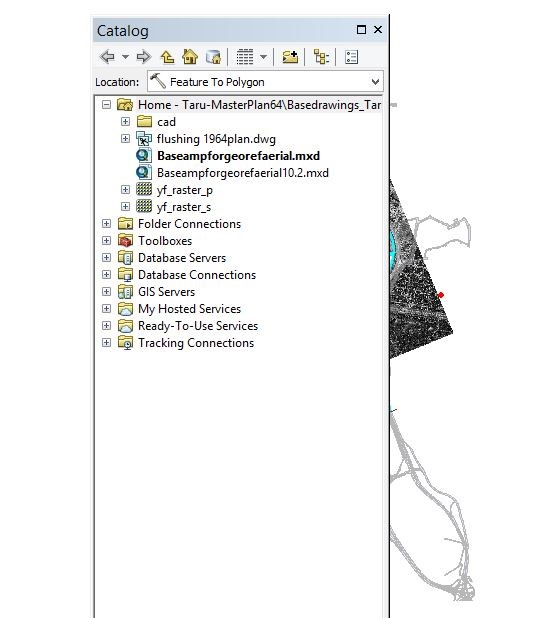
a) Import the Cad drawing into Arc map
In this case, since we had existing shapefiles, we created an arc map file where we imported relevant shapefiles existing in other databases. We then open the cad drawing via ArcCatalog in the file.
The file opens with the multiple layers listing type of features (lines, polygons, points etc.)
 b) Assign Coordinates
I used the define projection tool and assigned the same projection to the cad file as the other shapefiles for my project. Doing this allowed the file to be spatially located. In this case, the files still did not align.
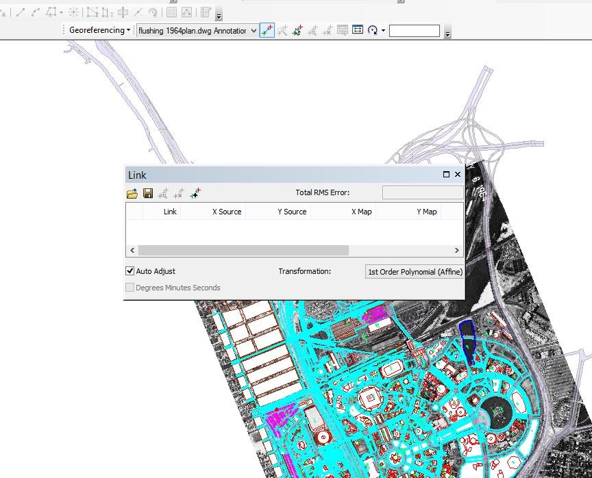
c) Geo-reference the File
In this case, the cad drawing needed to be aligned to other shapefiles. Since the data sources for both files were different, geo-referencing was a problem. Consequently, we imported a historic aerial of the 1964 world fair and aligned it first with the existing shape files using the geo-referencing tool.
We used 4 points on the outer edges to orient the plan. We then used the same method using parallel key points like the building edges to align the CAD drawing with the rest of the image.
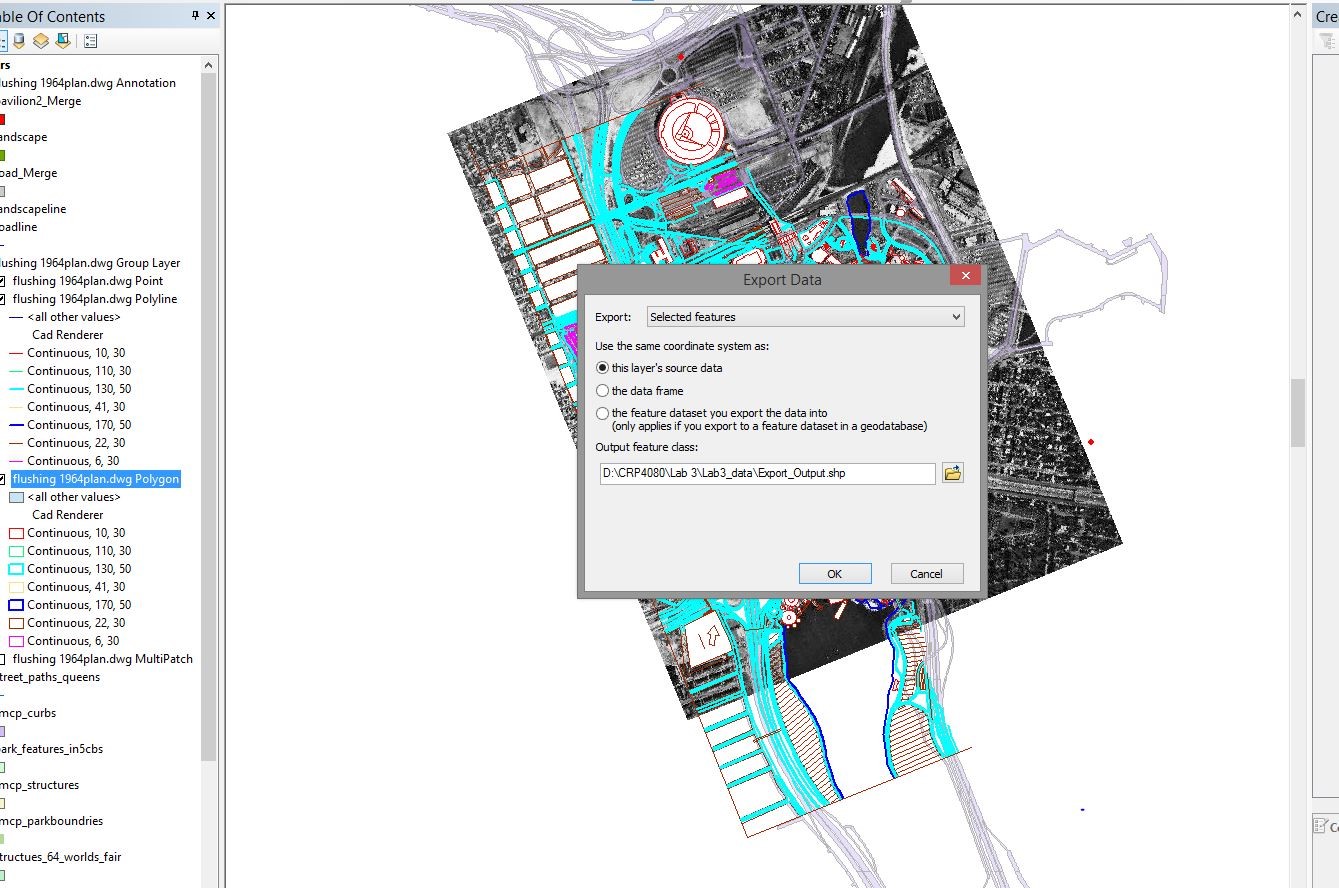
d) Converting given layers into separate Shape files
The assigned layers to the files do not manifest directly when the file is imported in ArcMap. The features have to be selected and saved as a shapefile. This can be done by selecting features by attributes. I used the SQl ‘Layer=pavilion’ to select all attributes drawn as pavilion. I did this for all the drawing features and saved the selected features as a separate shape file using “export and save as shp file.”
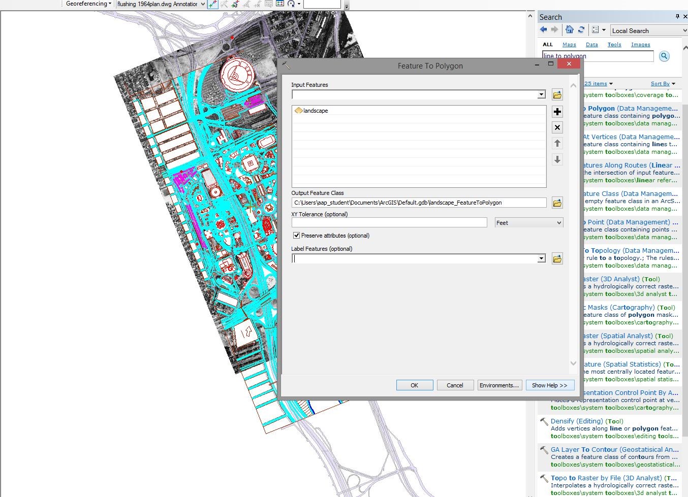
e) Converting Separate shapefiles into polygons and merging the files
All line and polygon features needed to be converted to polygon format for the shapefiles to be usable in GIS. The individual layers extracted from the cad drawing needed to be converted to a polygon format. This was done using the Feature to Polygon tool. Each of the extracted layers needed to converted to polygon format to be merged.
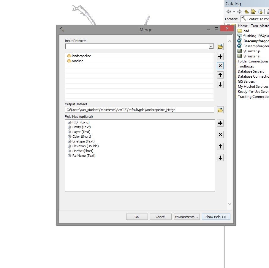
I then used the merge to select various shapefiles and merge them into a single layer. For example, all shapefiles consisting of the landscape features were merged in to a single shapefile. Similar process was repeated for other layers like pavilions etc.