by Feiyang Sun
This webpage documents some of the early steps we took to generate a geo-referenced terrain in CityEngine with DEM data and a Basemap from ArcGIS.
This included the following steps:
- Exporting geo-referenced tiff and jpg file from ArcMap
- Creating a CityEngine Scene and setting the coordinate system
- Creating Terrain from a TIFF
- Importing the Geodatabase and and Growing a Street Network from shapefile.
These steps require the use of ArcGIS and CityEngine. Previously, we had obtained a geodatabase from Quennell Rothschild & Partners, LLP and the New York City Parks Department. The geodatabase contained the street file reference below, as well as other datasets, which were created in the process of developing the Flushing Meadows Strategic Framework Plan.
Contents
Export geotagged tiff and jpg file from ArcMap
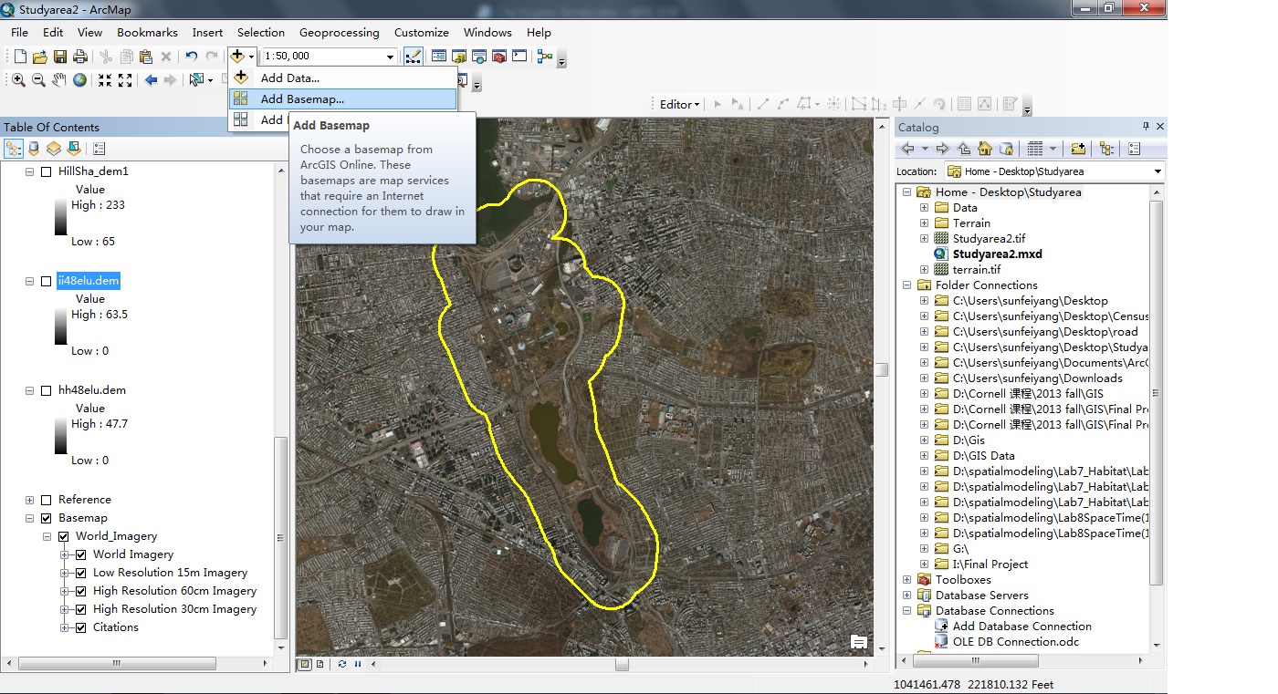
- The DEM for Queens County is downloaded from the Cornell University Geospatial Information Repository. Before doing anything, we should always check the coordinate system and make sure every layer is of the same projection. After the first inspection, we can add the basemap from the dropdown menu of the “Add Data” button.
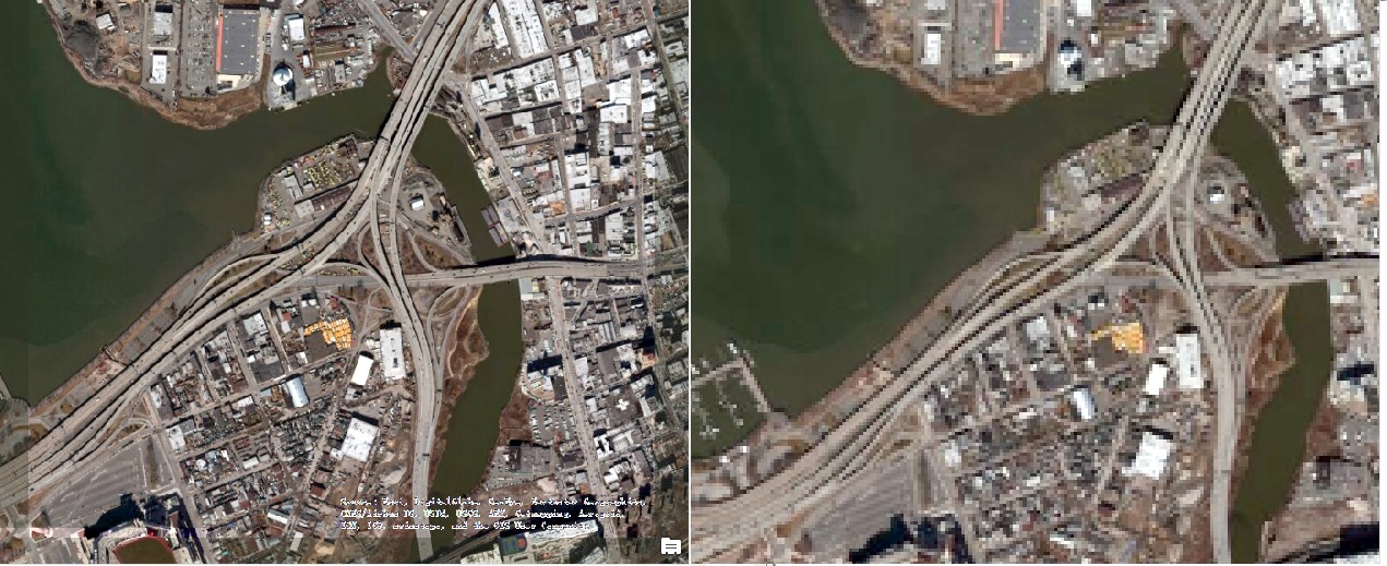
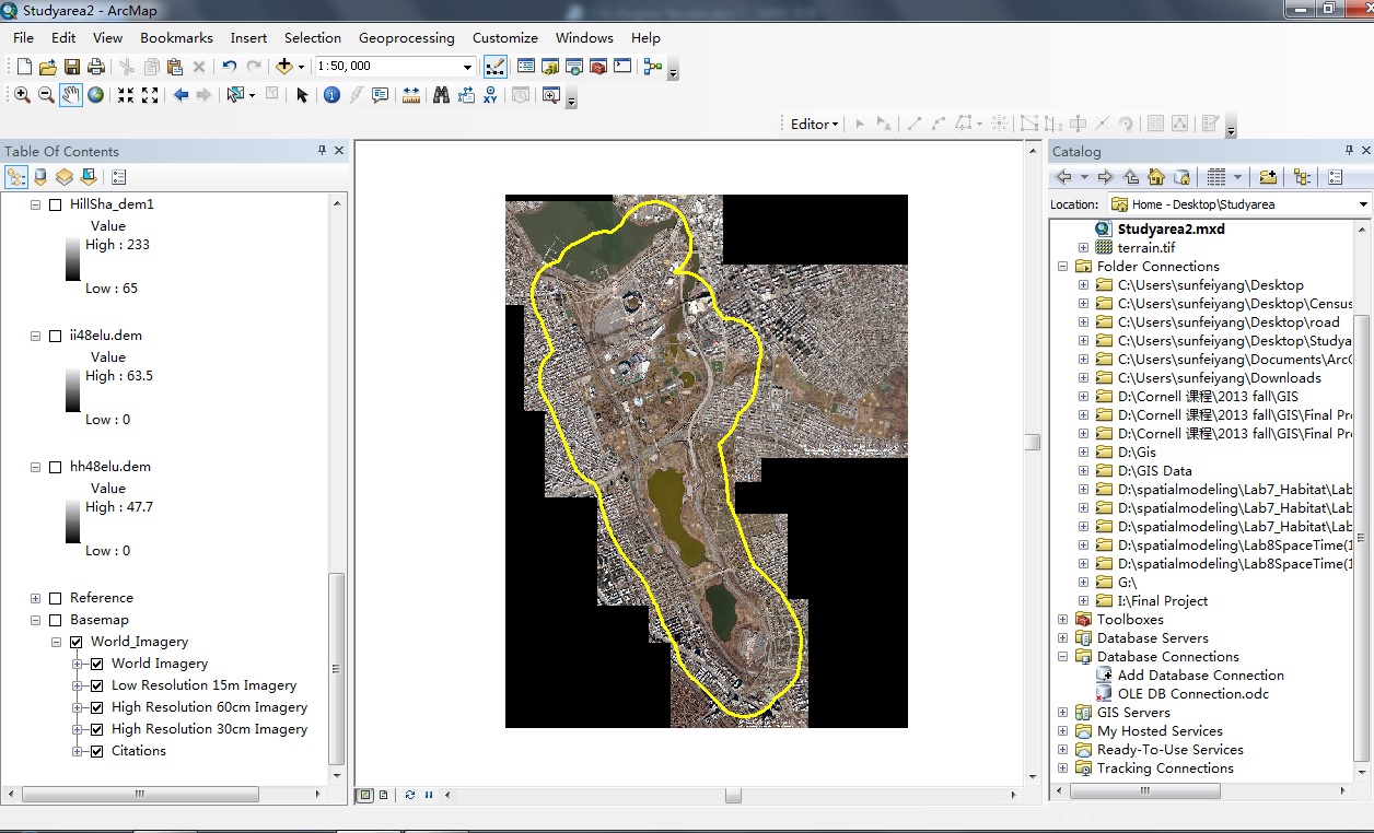
- Next step is to export the tiff file of both the basemap and the DEM with geoTIFF tags. In order to produce high-resolution tiff file, we need to export a small potion of the entire study area at a time for several times and then merge them together. The images below show a comparison between tiff file exported from the way mentioned above and a tiff file exported directly for the entire study area.
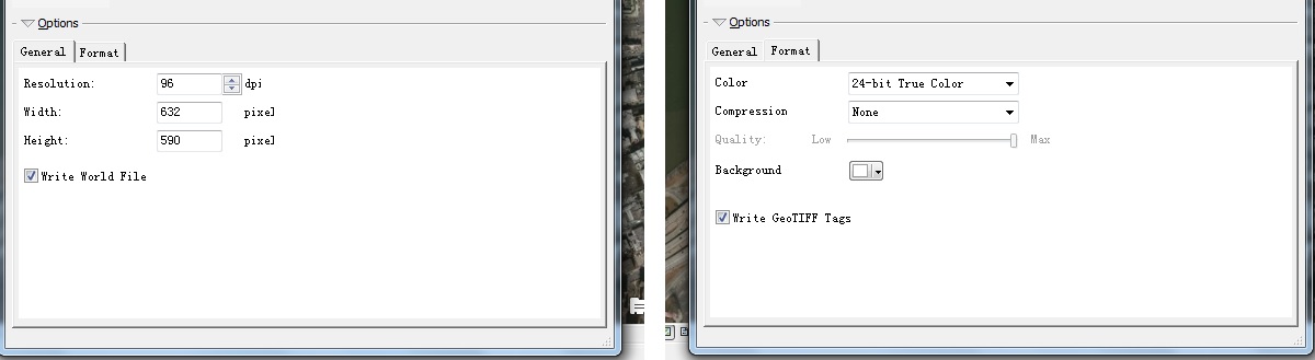
- In order to produce a high resolution tiff file, first, zoom in to a reasonable scale and use the “Export” button from the “File” dropdown menu. Choose tiff for the file type to save the file. In addition, in the Options box below, make sure that both the “Write World File” option in the General tag and the “Write GeoTIFF Tags” in the Format tag are checked. Add the new tiff files to ArcMap.
- Repeat the above operation several times to create enough tiff files that can cover the entire study area. Make sure that the adjacent tiff files overlay with each other to avoid blank space between tiff files. Organize the tiff files with numbers in order to trace them.

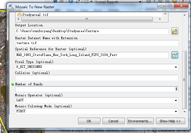
- Use the Mosaic to New Raster function to merge all the tiff files into a single layer. The function can be found through the “Search” function in ArcMap.
- In the dropdown list of Input Raster, select all the tiff files we just produced and add them one by one. The tiff file that is added first will appear in the bottom of the new layer and vice versa.
- In the Output Location, browse to the folder you want to save the file. In the Raster Dataset Name with Extension, enter the name of the file with .tif to save it as a tiff file. Next, in the Spatial Reference for Raster, choose the desired coordinate system. Finally, enter the Pixel_Type and Number of Bands according to the property of the tiff layers we are going to merge with.
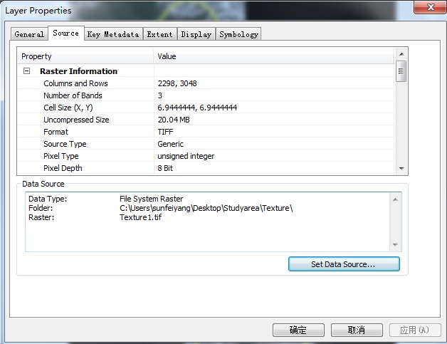
Right click any one of the tiff files we just created and go to the source to see the property of that tiff files.
After merging the tiff files, we can remove the original tiff files we created and just keep the one merged tiff file.
8. Next, we are going to divide the merged tiff file into smaller cells in order to export them to CityEngine. First, use the Draw tool to draw a square that covers the entire study area. The reason why we are creating square cells is because they are more compatible with CityEngine. 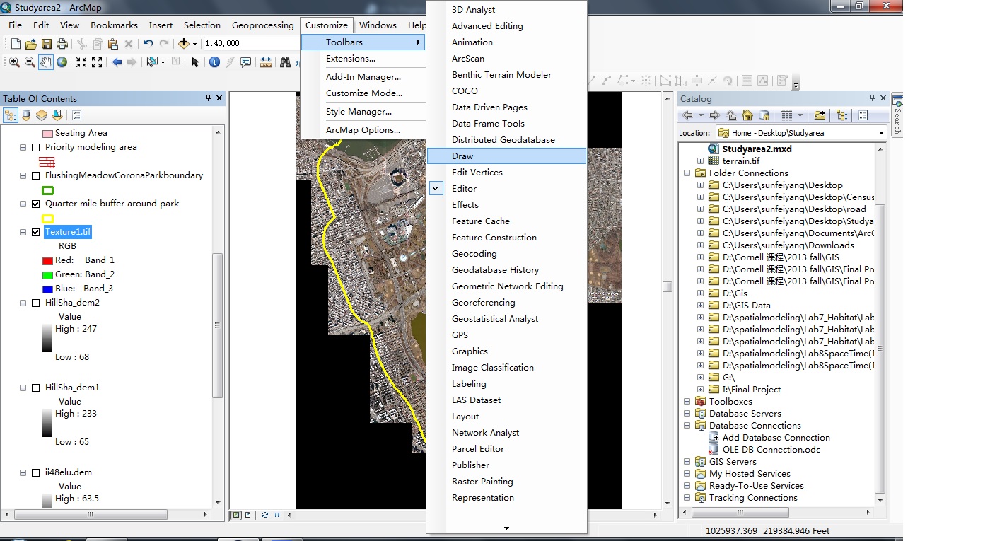
In order to do that, first draw a random rectangle that covers the study area. Right click the rectangle to open the “Property” menu. Under the Symbol column, set the fill color to no color and adjust the outline so that we can see the content under the square. Under the Size and Position column copy the value of the Width to the Height and check Preserve Aspect Ratio to create a square.
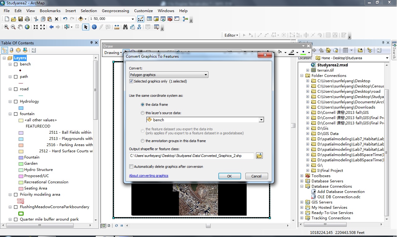
9. Convert the Graphic we just drew to feature. Save and add it to layer.

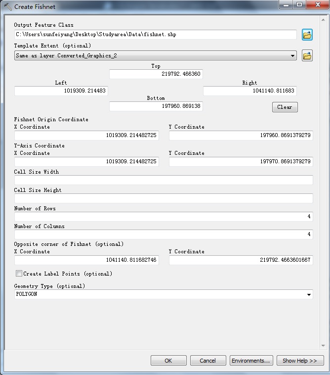
Use the Fishnet tool to divide the square we just created into cells. Fishnet tool can be found through “Search” function.

In the set up menu, select “Same as layer Converted_Graphic” for the Template Extent. Enter the number of Rows and Columns and uncheck the Create Label Point. The more cells we divide, the higher resolution we will get in CityEngine. Leave the rest as default.
Click OK and ArcMap will create a new layer called fishnet.
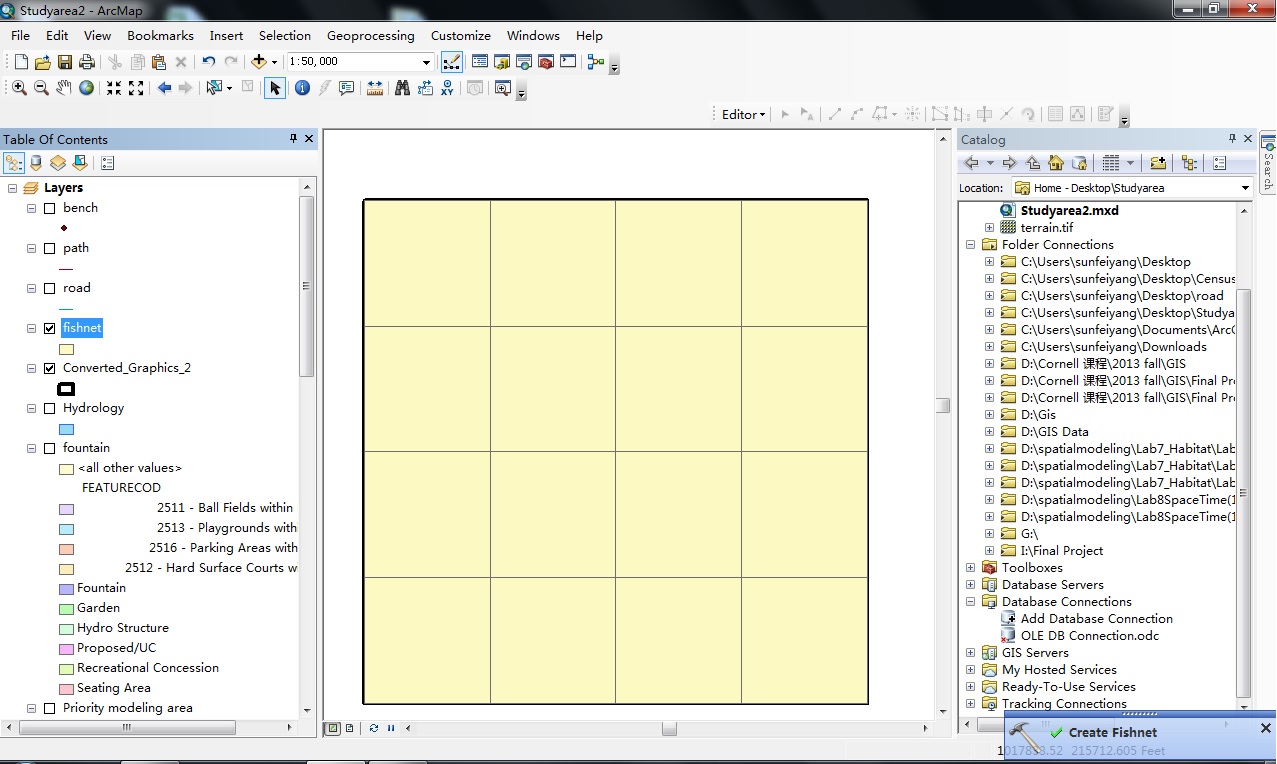
Right click the fishnet layer and convert it back to graphic.
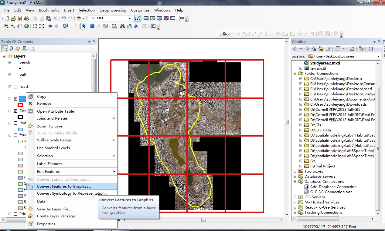 11. Select one cell at a time and right click the merged tiff file to export geo-referenced jpg for the terrain texture.
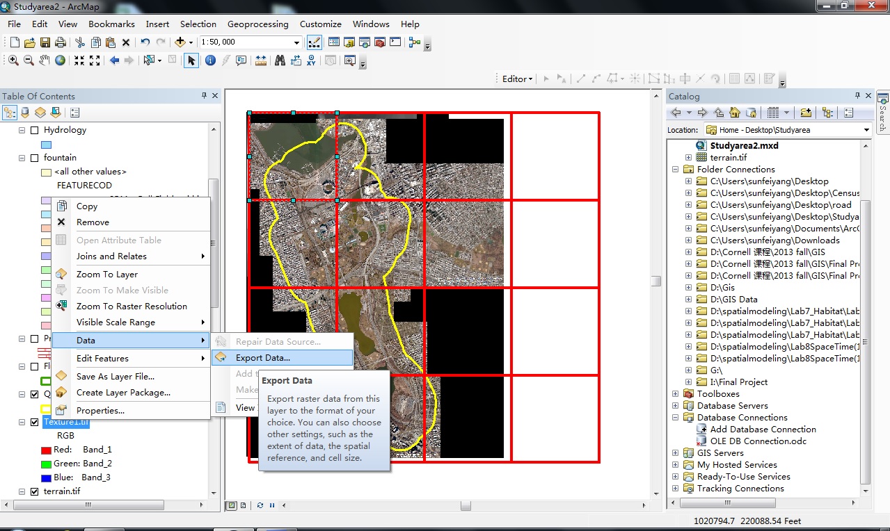
In the setup menu, select Data Frame (Current) for Spatial Reference, select JPG for Format and 100 for Compression Quality and check Use Renderer in Output Raster. Leave the rest as default. Repeat and export for each cell. It is unnecessary to export all cells, just cover the entire study area is enough. Make sure each JPG file is assigned a proper number in order to track it. The JPG files will be used as texture of the terrain in CityEngine. 
12. Repeat the same steps to export the DEM data into geo-referenced tiff files. However, this time use the TIFF for the format and DO NOT check the Use Renderer options. Again, keep every exported TIFF file coded in order to track them. The TIFF files will be used as height map of the terrain in CityEngine.

Now, we are ready to move on to CityEngine.
Creating a CityEngine Scene and Setting the Coordinate System.
1. First, we need to create a new CityEngine project. In CityEngine, elect “New” in the File dropdown menu.
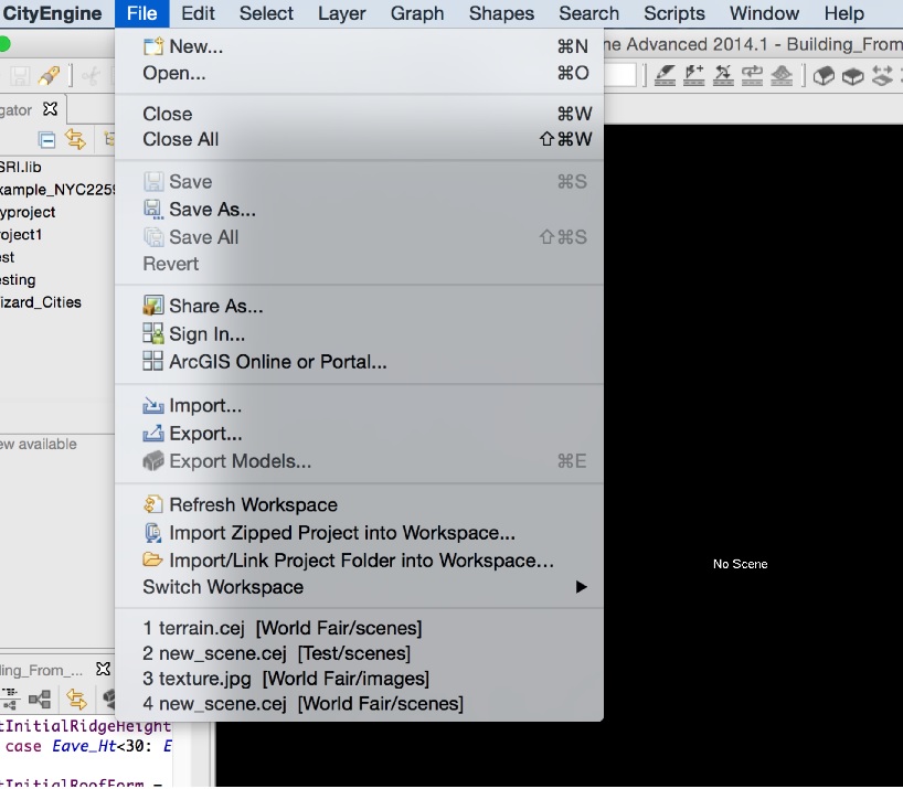
Select CityEngine project and click next and then finish.

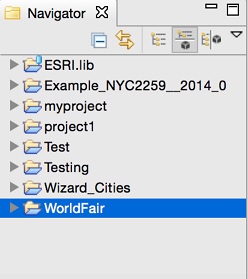
This will create a new folder under the Navigator.
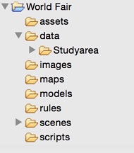
Expand the newly created project folder. Each project folder contains 8 folders: assets, data, images, maps, models, rules, scenes and scripts. Drag the folder that contains the Geo Data Base and all the exported files into the data folder.
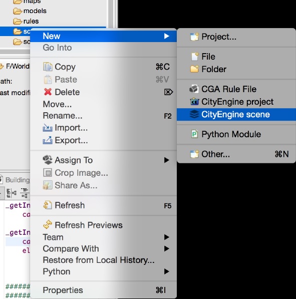
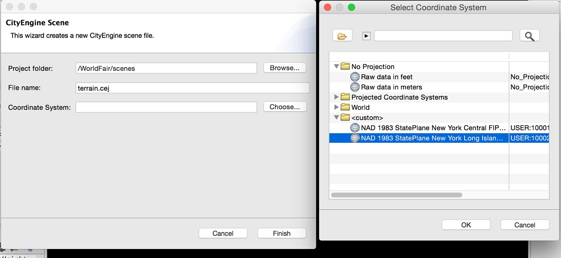
Create a CityEngine Scene. Right click the scenes folder and select New – CityEngine scene. This will enable us to create a new scene under the scenes folder.
3. In the pop-up window, enter file name and select the Coordinate System. Then click finish.
Create Terrain from TIFF
1. Find the TIFF files exported from ArcMap. In this document, I exported the TIFF file directly to the CityEngine folder. However, if the TIFF file is moved into the CityEngine folder from other folder, we should copy the .tfw file with it in order to keep the geo-referencing information. Right click the .tif file and select Import.

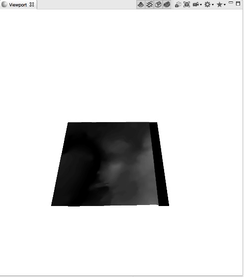
2. Keep everything as default in the popup window and click finish.
We can see that a block of terrain will be created in Viewpoint window.
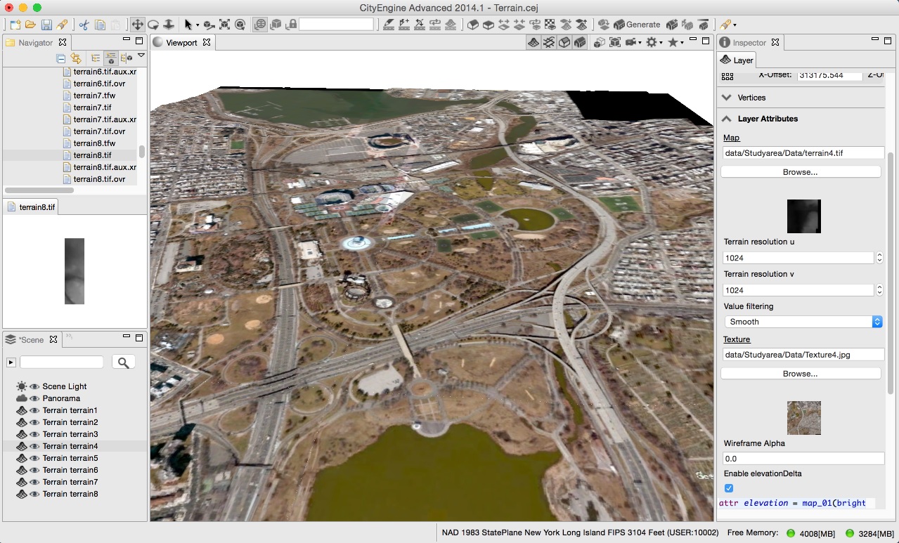
3. Import every TIFF file into CityEngine. Each of them is treated as a layer in CityEngine and can be selected in the Layer Editor at the bottom left of the screen.
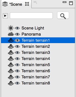
After selecting a Terrain layer, we can see its information and attributes in the Inspector at the top right of the screen.
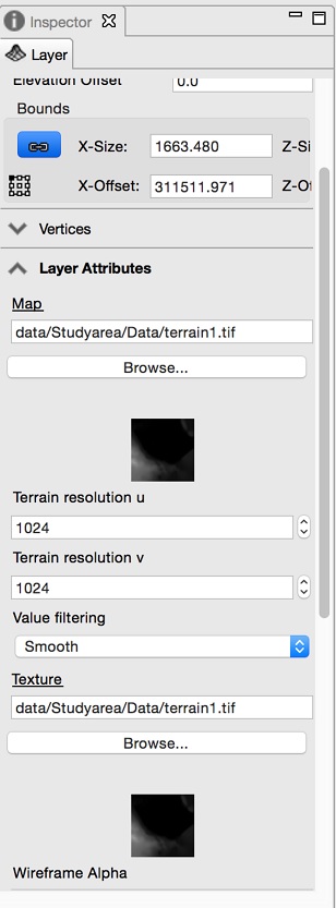
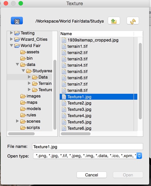
Under Texture column, click Browse. Select the corresponding JPG as texture.
Now we have successfully generated the terrain.
Import GeoDatabase (GDB) and Grow a Street Network from shapefile
1. Expand the File menu and select Import.
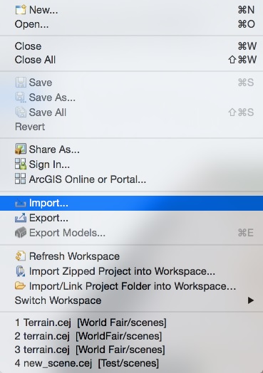
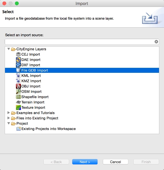
Select File GDB Import and import the GeoDatabase that contains the road shapefile.
2. Select the road shapefile. CityEngine will generate road network automatically. The road width is determined by the predefined width attribute in the attribute table of the shapefile.

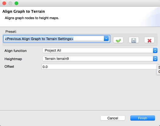
3. One potential problem with this approach is that the road network is only aligned to one terrain layer, and thus is not vertically aligned with other terrain layers. In order to fix the problem, we need first to go back to ArcMap and export the DEM of the entire study area as one single TIFF file. However, we do not need to export the texture for the terrain this time. After importing the TIFF file into CityEngine, right click on the road network layer and select Align Graph to Terrain.

In the popup window select the newly imported Terrain layer for the Heightmap option and leave everything else as default.
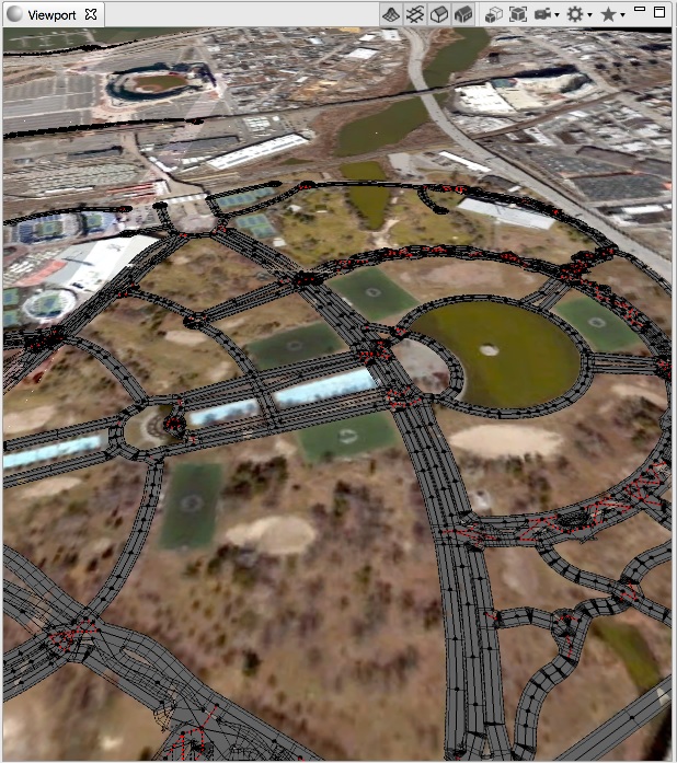
Now we have all the roads aligned perfectly to the terrain.
Very good, I loved the material, great work, congratulations.
Jean Rodrigues, Apaixonado por Tecnologia e profissional na área de Router CNC, São Paulo – SP
Jean Rodrigues, Apaixonado por Tecnologia e profissional na área de Router CNC, São Paulo – SP